I've started my adventure to build a Van's Aircraft RV14a. For several years, I've been planning to build an Experimental (homebuilt) airplane - once retired.
But first, I needed to get my Pilot's License. (Kinda key !) So... first things first: I retired March 2014 from Caterpillar - and started flying lessons in the Summer of 2014. Soloed a day after Christmas, and got my Private July 2015. Shop set up, tools acquisition, and practise kits during Fall launched me into my build starting Dec 31, 2015 !

I've chosen to build the RV14a since it's about 10% larger than Van's prior models - so it fits my 6'4" frame well. Van's is well known for great value & outstanding flying qualities. It's been a no brainer decision for me. A tour of their facilities and demo flight in Oct 2013 clinched the deal. My wife - also a pilot - exclaimed after her demo flight "retire NOW so you can build one of these". The RV14a fits my mission of a good compromise between cross country & aerobatics. Plus...I fit, too.

So far, one month into building, it's been rewarding. Very challenging, but certainly a learning experience. The builder community is terrific - as is Van's tech support. I'm finished with the Vert Stab and Rudder (Jan 2016). So... with a 5 month delivery lead time, I've ordered the Quick Build Wings and Fuselage.

I hope this blog assists other new builders, just like several others have been valuable to me. Plus it will serve to document my build step by step. Please drop me a line via the "contact me" form on lower RH margin.
Update: April 2020 relocated to Wickenburg, Az to escape Illinois winters.

Friday, December 7, 2018

Avionics

OAT wire routed, etc ( 3 hrs )

Routed OAT (outside air temp probe) from backside of G3X Touch display (GDU460) to center tunnel.  Required removal of 2 SB's at spar -- aarrrgghhh! (sensor too large to pass through), so split and re-installed.  Routed under LH seat area through ribs, then out large SB at fuselage side.  Next, fabricate several alum brackets to hold SBs supporting OAT wire.   Also routed "phone cable" ELT wire, and ADS-B/transponder RG400 coax antenna cable forward, then behind CB panel.  Connected to ELT model E-04 cockpit remote on IP (per Sect 53-02)m and to GTX 45R xpr.   Loosely routed LH and RH Common Fuse Harness, connecting for 1st time to IP harnesses.  Final positioning and securing tbd....
Lower left SB now has OAT wire passing from IP

OAT wiring under LH seat.  Next: add brackets w/ SB's next

Fuselage exit has large SB so sensor passes easily

LH Common Harness connected. 
OAT (white) and Static air line similar path, all
loosely arranged for now
RH Common Harness connected. 
ELT, and Transponder cables similar path,
loosely arranged for now


Thursday, December 6, 2018

Avionics

Static Air Line, etc  ( 3 hrs )

Added more red RTV (hi temp) at few places on engine baffles which showed up with "light test".   Routed coax antenna wire, ELT wire, and Static air line from rear bulkhead forward via center tunnel up to IP.  Used 16 SB750-10 per Sect 55-02. 
static air lower left,  antenna & ELT wires lower right
forward to Main Spar


next, route further forward and up behind CB panel

Wednesday, December 5, 2018

Avionics

Main Amps fuse link ( 2 hrs )

Re-worked "Main Amps" connection to Shunt on LH firewall (inside - so hard to reach, of course !).  Soldered in 26 ga wires on each 22 ga wire to act as "fuse links".  Would have been far easier if I'd realized this was recommended...prior to mounting shunt to firewall. 
after cutting "Main Amps" wire, soldered in length of 26 ga wire.
  I then looped so cable ties secured 22 ga wire to 22 ga wire.

re-installed to Shunt

Tuesday, December 4, 2018

Avionics

MAP sensor wired ( 2 hrs )

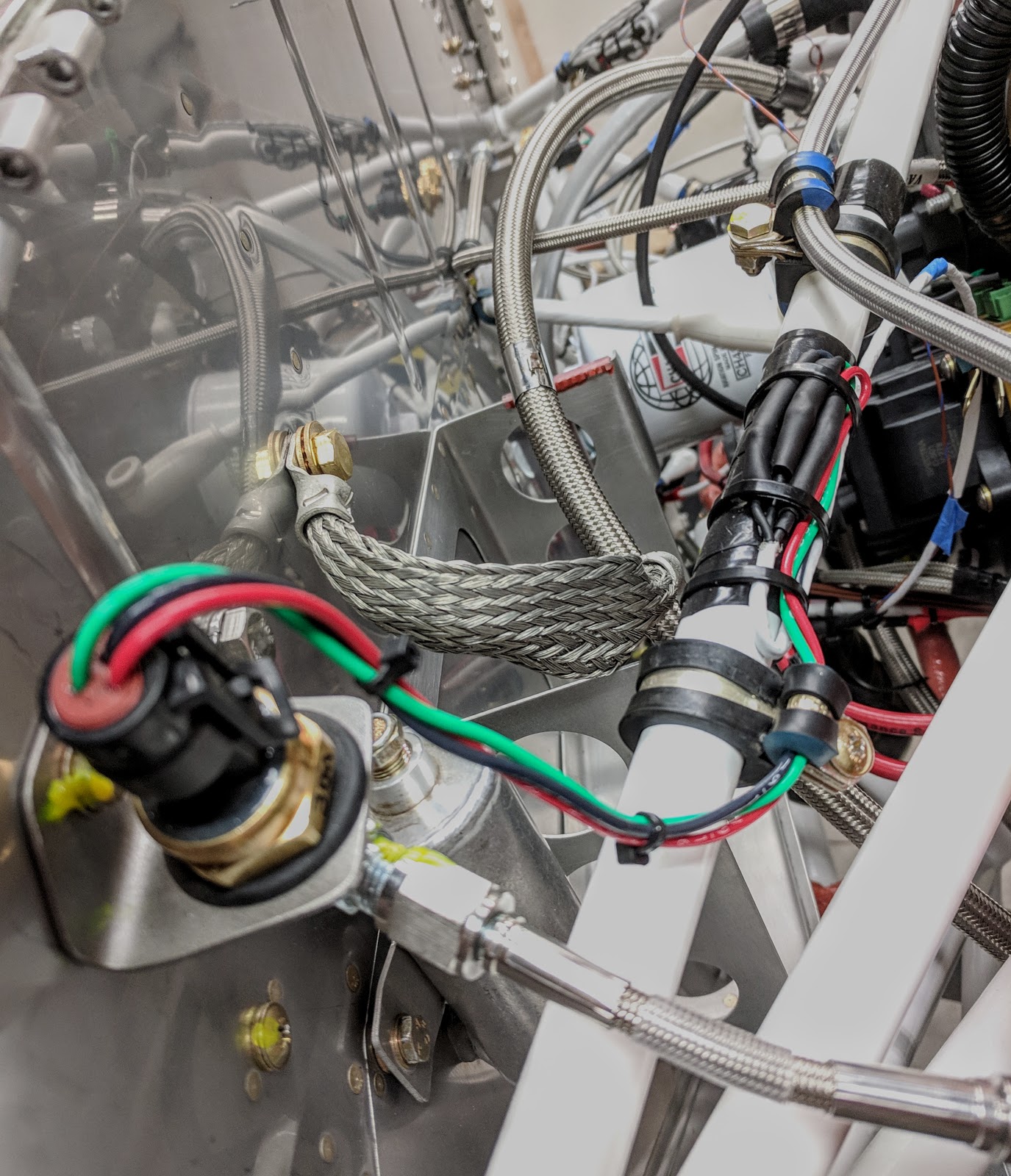
Connected MAP (manifold air pressure) sensor to wiring.  Looped extra wire for strain relief and "do-over" option.  Used several layers of heat shrink tubing to strengthen joint area, too.
after solder, 1st layer heat shrink. 
Two more layers ready, nested below

wrapped engine mount tube with silicone tape,
then secured wiring loops with cable ties
Added cushion clamp (to right in pic).

Monday, December 3, 2018

Avionics

EarthX battery warning via GAD27 ( 2 hrs )

Will soon be installing EarthX battery, model EXT680.  This LiFePO4 battery includes a BMS (battery mgmt sys) w/ LED battery fault light indicator to alert you to cell health and state of charge.  I'm wiring this warning into my G3X display via Garmin's GAD27 unit.  Added wire from Pin #13 in the J243 connector on the GAD27 to use the Discrete #5 function (programmable alert).  Stein Air provided pre-pinned brown/blu stripe wire.  I opened the 50 pin connector, inserted new pin into #13, routed in wire bundle to center, then forward to RH firewall opening along with MAP sensor wire.  Will connect once battery delivered.  [Note:  BMS includes over discharge protection, over charge protection, short circuit protection, excessive cranking protection (temperature sensing) in addition to integrated cell balancing technology] 
connector prior to
adding wire
partially disassembled. 

Re-assembled and re-installed onto GAD27. 
Whole process was easier than I'd anticipated
Ta-Dah !   wire for Discrete #5 now
ready to connect to EarthX at BMS


Saturday, December 1, 2018

Avionics

EAA Technical Counselor Inspection

Terry Moushon, EAA Tech Counselor visited Sat am, Dec 1 to inspect build quality ( his last inspection was Jan 23, 2018).   His mentoring and advise during his build of an Vans RV10 a couple years ago was major reason I was comfortable with starting my build.  He was impressed with progress, attention to quality and safety.  He spent a lot of time checking engine installation, wiring and the instrument panel.  I was pleased he documented a very positive report for EAA records.  Plus, he provided several good ideas for steps ahead, and updated me on a few maintenance items he's experienced now that he has over 300 hrs on his plane.  Thanks Terry !
After a thorough inspection, time for a pic.  Terry's on the left.

Friday, November 30, 2018

Avionics

P Mag connection ( 4 hrs )

While preparing to connect "P-Lead R" to right Mag, discovered statement in E-Mag install guide to separate plug leads.  Contacted Trent at E-Mag, who said up to 5" can be bundled, but more will cause induction coupling.  So....spent couple hours revising all lead wires for P Mag using the recommended 1/4" silicone tubing on cable ties to create separators.  Next, connected P Mag per p. 26 schematic in Install Guide and Stein Air's schematic:  "P-Lead R" to Pin 4, with shield wire connected to Pin 1 as ground (added separate wire from engine stud nearby also to Pin 1)  This creates 3 ground paths including P-Mag itself bolted to engine case.   "P Mag 3A" connected to Pin 5, and Tach Output (white wire only) connected to Pin 6.   Finally, aligned blast tube to insure directly on "neck" area of P Mag per Install Guide.  Wrapped oil line with silicone tape (red) prior to applying cable ties.
revised so P Mag leads are separated...RH side
note in E-Mag install guide.


LH side

LH side.  Only minimal contact at cushion
clamps, far less than 5" 

Pin 1, 4, 5 and 6 connected.
Jumper was pre-installed between 2 and 3.
Pin 1, 4, 5 and 6 connected.
Jumper was pre-installed between 2 and 3.


connector re-installed. Ground terminal "loose"
at stud at unused aux drive...for now. 

p 26 schematic in E-Mag Install Guide for P Mag connections 

Blast tube positioned directly blowing on P Mag
"neck".   Red silicone tape protecting Oil Line
blast tube positioned per E-Mag
instructions